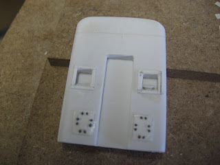
The cab end wall propped in place for reference.This is the MDF jig I made for the corner steps and a soldered up part that has been covered with diamond plate. I am going to use this on some, but not all, of the steps to indicate replacement units. The rest will be plain brass representing welded steel pieces. The two center pieces are removeable while the outer two are CA'd to the bottom as well as the wide lower piece.
Thursday, December 24, 2009
House of Cards
Here is the first photo of the hood assembley set in place on the frame "house of cards" fashion. Nothing is glued to anything. I'm just praying nobody opens the door and creates a breeze! The hood panels are not anywhere near finished, of course, but I need a little encouragement along the way and this is an easy way to get it. At least it is beginning to look like the little beasts.
Monday, December 14, 2009
Frame and Trucks Mated
On a very preliminary basis the trucks have been mated to the frame. As you can see the pins (1/8" styrene) will have to be trimmed to clear shafts and u-joints and enough left over to allow for a clip of some kind to retain the truck assembly. The pins seem strong enough. I have been carrying the whole assembly around by them. I still have to make the plastic shims to seperate the metal pad on the gear box from the brass bolster to isolate things electrically, and fabricate the new bronze wipers. Also I have to devise some method to attach the side frames to the gear box but that looks like a straight forward deal. There are a number of places to bolt or glue things.
From the end view it would be hard to deny that this is a NARROW gauge locomotive. 30" looks pretty skinny. The pictures were shot on the aft deck of my wife's new baby trimaran, the only flat spot left in my shop!
Saturday, December 12, 2009
Progress
The 1/8" styrene posts have been epoxied in place in the gearboxes. They will have to be trimmed to clear the drive shafts and u-joints later. Some clearancing had to be done on the interior to allow the half's to go back together but not much. The Dremel came in handy. There seems to be plenty of swing for the trucks to negotiate a very small radius curve. I have not yet made the wipers for the new electrical pick up system because I don't have any phosphor bronze sheet metal and have not yet ordered any. Too close to Christmas. It is a madhouse with visiting relatives etc. I am pleased with the relative ease with which the trucks have so far yielded to my wishes. No NWSL wheels yet.
I glued the deck onto the frame today as promised. It worked out fine. I hope to get to the skirts tomorrow. Maybe a battery box and fuel tank next week. A new styrene frame should pop out this weekend.
The end beams will have the main air hoses and angle cocks added this weekend. They are becoming delicate pieces. They will not be finished until I get an order from Precision Scale, probably not until the beginning of the new year.
I made aluminum jigs for making the grab irons. The first of several I intend to make for that purpose on the rest of the model. These were just for the end beams or pilots, if you will.
I started over with the nose master. Sort of a built up thing like a model airplane. So far I am happy with it. We'll see how it goes. It needs some 1/4" square tubing I'll have to order for the sand filler openings and it will be skinned with .010 styrene. I like the look of the thin styrene when trying to duplicate sheet metal as it buckles most prototypically. Wish I could find .005 thick stuff.
Monday, December 7, 2009
U6B Bolsters
The bolsters are mounted thanks to Micro Fasteners. They sent the tap drills so fast I thought they had made a mistake. No set was required either and the price was cheap.
You can see the .040 deck is in place but not yet attached. I am working on the trucks, modifying them for a pin type mounting and changing the electrical pick up scheme. When that is done I'll go ahead and glue the deck in position.
Still at the nose master. The aluminum is working out so far. Got my fingers crossed.
About to order a bunch of detail stuff from Precision Scale. Real good stuff!
My wheels have yet to show up from NWSL so I'm a little bummed out about that and am still waiting for a new Grandt Line order. I'm sorta' focused on the nose out of necessity.
A Plastruct order should arrive next week with some 3/16" square pieces that will allow me to get a new all plastic unit started.
Friday, November 27, 2009
Layout Ideas and Theory
Most modelers, urged on by the popular modeling press seem mass aimed at “prototype operation” as a be all end to the hobby. The ideas behind this movement are fine as far as it goes and as long as people are having fun at what they perceive are “prototypical operations” it is ok by me. I am not here to dump water on anyone’s fun.
I have a different take on the hobby and it comes from a long history of actual “prototype operation”. Most modelers seem to want to be real locomotive engineers. At least on the surface. Maybe you all are smarter than I at first thought. When I hear “prototype operation” I get a chill up and down my spine. I spent 38 years running freight trains ( and an occasional passenger train) for the Southern Pacific and, oh yes, big yellow. I am currently writing a book about those years and a lot of it has to do with explaining how physically exhausted a human being can get and still function. Function in an environment where the outside temperatures are over 120 degrees and the cab temperatures are 150 degrees. The air conditioner quit. Before that there were no air conditioners. The Sonora desert is below freezing a lot of the year, believe it or not. For many years not a single pay period went by that I wasn’t shorted. Some of those disputes took years to resolve. The company was earning interest on that money. When I was finally paid I got not a single penny of that interest. Some of those disputes were never settled. When I retired, through mergers and unsettled claims I had lost over $50,000. None of that was ever fun.
U6B Cont....
The engine compartment hood ready for the mold box. The access doors ( and there are two of them) will be added after the parts come out of the molds. The opening will be filled with brass wire mesh and cover radiator details as well as what appears to be a walk way down the middle.
The underframe with the bolsters propped in the approximate mount position. It is impossible to mount the trucks in the correct center to center position due to interference with the coupler draft gear box. Maybe a custom built drive would solve this. Note the dimples for the tap drill locations. Still waiting for my drill bit. Some things can't be speeded up.
I am now considering making the nose master out of a solid block of aluminum. Should work? Until next time.............
Thursday, November 26, 2009
Maybe Some Progress
These new photo's point up some of the work I've done recently but are a better teaching tool. The end beam is fine but the nose is supposed to be a master for casting and it looked fine to me until the camera revealed the obvious flaws. It goes to the scrap pile. Note the drop step. This is the underside. The top side will be overlaid with diamond tread. It will actually operate.
I am still working on the underframe. Cut the bolsters and prepared to drill and tap for 4-40 screws to hold them in place only to discover I was missing the #43 drill required for that tap size. Had the 42 and 44 though. No one has that locally I could find, after burning out my cell phone battery, so I had to order from Micro-Mark....in a set, naturally.
Still have MU hoses to add to the end beams and big air plus MU cable recepticles and grab irons but I'm getting there. I work at it everyday when practicable.
Still waiting on the wheel sets from NWSL..........
Saturday, November 21, 2009
U6B Hood Top
Success! I managed to get the profile into the top of the hood ok. It took some doing and patience but it is now about ready to be afixed into the casting box. I still want to do some polishing on it yet. All additional details will be added on after the castings come out of the molds.
I use 1/2"x3/4" aluminum angle for the box sides. They cut easily on the table saw, are square, offer two depths for the rubber molds and easy clamping surfaces. Also a smooth and consistant surface for leveling the back of the mold.
I started work on the front (nose) master. There is a access door and sand box hatches as well as light fixtures there and a bunch of NBW detail. I like to spread the work around as I have a low boredom threshhold. I think I'll get back to the underframe tomorrow unless Grandt Line shows up with some parts in which case I'll return to the end plates and get the coupler situation resolved. Kadee delivered their goodies a few days ago.
I should have pictures posted on this new stuff within a day or so.
Engine Hood
I found some photo's of the roof tops of a U6B so I was able to begin work on that part. It will be a master so I can cast more of them for the next two to follow. Also found a reference to a hand brake location on the cab end of the engine but still no pictures.
Have begun work on the engine hood. A styrene base with brass overlays for the doors and panels. See through mesh for the radiator intakes and outlets. The fan is pretty much hidden so I’ll not bother with powering it up. One of the engine room doors will stand open to see the cat engine which will hide the motor and the cover over the flywheel will stand in as the generator.
No new parts have arrived in the mail so no work has been done on the end plates. I don't have a handy local hobby shop that I can run to get parts so planning ahead is critical to keep progress flowing. The nearest good place is 100 miles away in Phoenix.
I am happy with the work so far. I'll keep you posted.
U6B Engine Hood
Work continues on the U6B with the engine hood, forward, right hand side. It is a styrene .040 sub base with .005 brass overlays of the engine room access doors and panels that cover the fan and radiator compartments. The air intake is framed with brass channel that captures the wire see thru mesh. There is much more detail to be added including hinges and bolt detail but it has been a good start.
The first engine room door to the left will stand open and have additional interior bracing detail and will reveal engine room details.
I also got started on the long hood roof or top by laminating an 1/8" and .060 styrene sheet together to get the proper thickness and cut out the radiator air outlet. The sections get pretty thin and I'm still tinkering with it. When I get it right I'll try putting the proper contour into it which may prove fatal, in which case I may have to try another tack. Wish me luck. If this doesn't work I may try it in wood, seal it, and then take the castings from that. Acrylic sealants work real well for taking the wood grain out of the picture.
I'm trying to finish up my wife's new sailing tri-maran at the same time so it's difficult to keep projects separated! There's nothing like being retired.
I found some photo's of the roof tops of a U6B so I was able to begin work on that part. It will be a master so I can cast more of them for the next two to follow. Also found a reference to a hand brake location on the cab end of the engine but still no pictures.
Have begun work on the engine hood. A styrene base with brass overlays for the doors and panels. See through mesh for the radiator intakes and outlets. The fan is pretty much hidden so I’ll not bother with powering it up. One of the engine room doors will stand open to see the cat engine which will hide the motor and the cover over the flywheel will stand in as the generator.
No new parts have arrived in the mail so no work has been done on the end plates. I don't have a handy local hobby shop that I can run to get parts so planning ahead is critical to keep progress flowing. The nearest good place is 100 miles away in Phoenix.
I am happy with the work so far. I'll keep you posted.
Have begun work on the engine hood. A styrene base with brass overlays for the doors and panels. See through mesh for the radiator intakes and outlets. The fan is pretty much hidden so I’ll not bother with powering it up. One of the engine room doors will stand open to see the cat engine which will hide the motor and the cover over the flywheel will stand in as the generator.
No new parts have arrived in the mail so no work has been done on the end plates. I don't have a handy local hobby shop that I can run to get parts so planning ahead is critical to keep progress flowing. The nearest good place is 100 miles away in Phoenix.
I am happy with the work so far. I'll keep you posted.
U6B
This has been and continues to be an interesting project. Small GE engines have fascinated me since the vacation my family took to the Owens valley when I was a kid. The SP narrow gauge 50 tonner was working in Owenyo the day we were there. My dad had worked the branch as a brakeman off the extra board in Sparks, Nevada and he was a modeler of great skill. For him, this was a research trip, it was just fun for the rest of us.
When I began research for the U6B I found both too little and too much information. Too much because there are thousands of small GE engines out there and an awful lot of them look alike which confuses identification. Most photo’s are captioned by tonnage, an odd measure of a locomotive to my way of thinking but probably sparked by the 44 tonner which had political and management implications. The other weights of locomotives didn’t and they tell us very little about them.
A search of the internet turned up very little about the U6B except a fine web site from South Africa on a variation of the engine with a short hood and very different trucks the likes of which I have never seen and which bear no resemblance to the “stock” plate type that seems to be typical of the breed. There are many references to the U6B and vague references to a mysterious U4B but precious few photo’s and no drawings beyond a couple of general arrangement sketches with no top views. Every drawing sports different dimensions!. Most photo’s show different door arrangements and vent positions. No photo that I have seen has ever shown a hand brake. GE’s big engines locate the handbrakes on the engineers side of the unit somewhere so I will make that assumption but can’t back it up with fact.
Subscribe to:
Posts (Atom)