Wednesday, November 24, 2010

Layout Progress

While this image is not very good it will serve as a general view of the overall layout design. The drawing has been erased more times than I care to remember and is still in the process of change.  If you have been following this blog you will recognize that the left side of the sketch has already been modified ! At least you all have an overall view of the extent of the whole layout.
I overcame a major obstacle last week by the removal
of a 275 gallon fuel tank that was within the boudaries of the harbor scene on the right side.
It took the new owner of the tank and me several hours of hard labor to get it out of the basement but it is finally done. I immediately began putting down the sills for the new walls in that section that divides off the water heater and the ancient oil heater.
This is the engine service area around Bridge, Oregon. The scene will consist of mountain sloping upwards toward the backdrop covered with pines and spruce etc. the track and structures in the foreground. I am experimenting with the valance.  The wavy cut is to prevent distraction of a straight line as it will be painted a sky scene exactly like the backdrop.  I am hoping to add depth instead of "framing" the scene in the normal way. If it doesn't work out I'll just remove it and cut it straight and redo it the "normal" way but I think this is worth a try.  Nothing ventured nothing gained. The valance also hides the lighting which I have also finished wiring for this area. Haven't turned it on yet because I don't have the fixtures installed. Yes, that's a outlet box that hasn't been wired .  It comes off the wiring for the room behind the wall (workshop). 

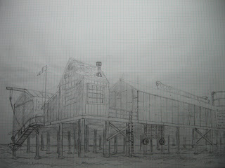
This is a sketch of the end of the wharf at Bandon Harbor.  Just something to tweek the appetite for structure building and visualization.  The module of the wharf is 30 inches by 9 feet ! Lot of stuff to build....
Am I a lucky boy or what? My wife bought me this Bachmann Shay for my birthday!! Can't wait to get at it with the airbrush and chalks to dirty it up a little......

Sunday, October 31, 2010

A Tutorial

The Um6b has a set of dropped grab irons on the side of the unit just forward of the cooling air intake that serves as a ladder to the roof.  They are pesky little dudes to make because they must be as nearly identical as possible. To be otherwise would make the oddballs stand out like a sore thumb. In addition they have to be mounted absolutely vertical and without variation, in line, one above the other. Eyeballing these babies is out of the question, at least with my eyesight ! The solution is a set of jigs and fixtures.  They are simple to make, don't require much time or effort and are cheap.
The first is this simple aluminum angle 1/8" thick by 1"x1" x4" long with a .025 hole that is 17" from the notch filed in the end. This thing makes 18" long grab irons. Bend the wire stock over the notch as far as you can (I use .0225 brass) using your thumb and forefinger.  It won't make 90 degrees so you'll have to adjust it with a pair of pliers.  Use the inside of the aluminum angle as a guide but be careful as all extruded angle isn't necessarily 90 degrees either.  When you buy it check, they won,t mind.
When you get it square, insert it in the hole and line up the unbent end over the notch.  Bend it the same way you did the first bend.
Sorry about the blurry photo but you should be able to see enough to get the idea. The bend should come out about like the next picture.

Square this new bend up with the pliers using the aluminum angle as a reference. When that's done turn the wire sideways and check that it is not twisted. You should only be able to see one wire as in the next photo.  This is critical.  If you get things twisted the finished grab irons will never look right.  Take the time to tweak them into shape.

In the photo below you'll see that I have made two notches in the edge of the aluminum angle. They are 18" apart. Just wide enough to hold the bent up grab iron, because we need to make another bend in both "legs" to get the drop in the finished piece. That bend has to be uniform in length.

As you can see I use another piece of angle to back up the grab iron while it is in the notches and then I use a flat needle file to hold it down and simply bend the legs over the edge of the angle. Voila! Consistant, uniform length bends. You have to make final adjustments to the bend angles with pliers as usual and all the bends must be parallel and square with each other or they won't set properly in the pre drilled holes.  We're not finished yet, because those holes are just as important as the grab irons themselves and we need a couple more jigs to get this done.

This is the drill guide.  It was made from .020 styrene and the cross member from .125 square styrene.  The blade should have been .040.  This was really too flexible but I made it work. Very carefull layout work pays dividends in the end.  I centerpunch my holes with a pin using a magnifying glass and am very carefull to make sure I drill the holes as verically as I can.  If you have a sensitive drill press, use it. These were done with a pin vise using a #74 drill. The thing is glued together with styrene adhesive.  Be absolutely sure it is acurately positioned before glueing.
This is how it works.  Notice the holes next to the guide below the grab iron.  It works!!  I clamped the guide in place with some small spring clamps. Probably a good idea.  If you tried to hold it with your fingers it would most likely drift.

This is the last piece of fixture you need. Simply a piece of .060 styrene about 15" wide to space the grab irons a uniform distance from the surface while glueing. I used CYA from the inside of the car body. If things are a tiny bit out of whack you can bend the wire into shape at this stage.  If it is a lot out of whack, pull the offending grab out and make a new one. When the adhesive sets, pull the spacer out,

and admire your work !  Still needed is the nut bolt washer detail at the top of each leg.

Does anybody really need this? I don't know but it was kinda' fun to do and so I may do some more as I progress with this model.  I notice some strange effects with the photo's. The grab irons are perfectly straight as is the roof line of the engine.  I don't do Photo Shop so don't know how to fix those things.  My wife is good at it so I might have her take a shot at it when she gets some time.  Might not be worth the effort. At any rate, the moral of the story is, jigs are simple and effective and mostly cost very little. Sometimes the effort to think of a way to do them is much more than the effort required to turn out the final product. Sometimes they are the only way.

Wednesday, October 27, 2010

Modifying the Modified

Or in other words Plan "C". You'll note that the car repair facilities have been moved to the yard.  It will be served with dual gauge track . Again, "reach in" and depth allowed for scenery was at the tipping point so I felt it necessary to make this change.  There is also a mistake in the left to right dimension of the room.  It is actually 18" wider than on this drawing. Don't know how that happened but stuff does sometimes. It doesn't effect the overall design. Just imagine the yard tracks with a foot and a half more straight track stuck into the middle. When I am standing in the basement in the middle of this I can "see" the scenery much easier than on the drawing and I think this inability to translate the 2 dimension into three is why I keep having to change things. I also think it is why I look at layout design as sculpture more than an engineering or operational concept.  And this is just the ten foot end of a nearly 40 foot long sculpture.  Yikes!
When I am standing in the middle of this I see sight lines with trees and mountains and strucures and where water is or has been and where the trains must go. Where the lighting must be to avoid weird shadows and the structure to hold it all up. The backdrops are easier to visualize and I can see how other parts of the layout can help backdrop this section to help form a larger vista. I think that is going to turn out to be a key element in the overall impact of this project. The larger vista.

Monday, October 25, 2010

A Tribute to Athearn and A Story About Trucks

I received the worm drive assemblies from Athearn shortly after I ordered them even though they tell you it will be 6 weeks for parts delivery. Never more than 10 days. This time the worm drive assemblies were minus the gear box covers. I say that with some trepidation.  In the exploded view of the SD40 parts diagram it shows the covers as part of the "assembly".  I assumed they were.  When they didn't show up I e-mailed Athearn and asked if they were not part and did I need to order them seperately.  They sent me three new covers  with  a note attached saying they were available seperately for $8.95 a dozen and were not part of the "assembly". Thank you Athearn guys. A nice gesture which won't be forgotten.
This first picture shows how much I trimmed the styrene post I previously glued into the truck frame. It is actually flush with the cross member(Bolster).  I am beginning to think this was a mistake in material selection.  This post takes all the stress of draw bar pull and I don't think it will last very long. We'll see. At this point I was concerned about clearances .  As the next photo shows everything worked out just fine but it IS really close under there.  I cleaned up the u-joint castings just to make sure but there is no intereference.
I did have to make a modification to the gear box cover.  It would not snap shut over the gear tower when I installed the truck in the underframe. If you look closely at the two covers side by side you'll notice that the left one is taller.  I took about .010" out of the right hand one.  It then fit just fine and did not interfere with the worm gear . Previously I was concerned with finding a way to keep the trucks held in place with some sort of a clip arrangement.  Well, you can see by the slightly out of focus fourth photo of the truck mounted with the cover in place that the protruding arms do a very nice job of just that. Athearn to the rescue again!!Some surgery has to be done on the deck to allow swing room for the trucks and more room for the drive shaft and flywheels but this was a good day in the history of these models as I am convinced that they are going to run very well and reliably now without too much further problems.  I still have to deal with electrical pick ups but that shouldn't be too much of a problem.....and then the sound systems, of course.  That's a whole new univeerse for me.

The last photo shows the roof master mounted on a 1/8" aluminum plate.  I ran out of similar thickness styrene so I ran out in the shop and hacked this out of some old airplane stuff I had lying around. Aluminum like this (6061T6) is machineable with woodworking tools, I cut it on my table saw, is very stiff in this thickness and I can debond it if I really want to after I'm done with it . It should make an excellent base for casting. I'm still tinkering with the master, filling small holes and such.  As you can see, all the warp has been removed by bonding it to the plate with CYA.


Thursday, October 21, 2010

New Benchwork

This is the new bench work for the engine service area referenced on the new sketch for Bridge, Oregon. It has been permanently attached to the walls.  New sheetrock work has been accomplished including the "lid".  The front of the bench will be finished, probably with a curtain in this area. Yet to be determined.

Archer Louvered Vents

These are the Archer Vents (Resin castings on decal paper) added to both engines in the appropriate places. (Battery boxes, doors and accessory panels)  While they are not perfect, they are very good and about the only way I was going to get them on these models without making seperate castings from another master and applying them that way.  This is much easier and quicker.  I work slowly and this took about an hour to do both sides of both units.  For some reason or other the vents on the brass substrate looks "cleaner" but I suppose it won't matter when painted and weathered.  I am very happy with this product so far. I'll be ordering some "GE" style tread plate and some more "Weld bead" soon.
Athearn is sending the covers for the worm drive assemblies but I still haven't  received the motors from Micro Mark. It looks like everything is going to fit in the available space but I have some surgery to do on the styrene deck to get clearance for the u-joints and drive shafts.  There is still some question about the main reservoirs which are located inside the cooling air intake screens whether they will clear the power truck "swing".  Hope so, because I'm counting on them to hide the upper gear tower.  When that is solved  I can go about devising a hold down system for the long hood(s).  Some sort of a machine screw and  tapped styrene block arrangement I think.  Engineering on the fly !

Monday, October 11, 2010

The engine service and car repair area benchwork installation

Layout Design Plan "B"

A funny thing happened on the way to installing benchwork under the portion of the layout shown by the previous sketch in this Blog. The switches on the yard lead were obviously out of reach !  So far out of reach that even if I stood on a stool or step ladder I WAS NOT GOING TO BE ABLE TO REACH THEM ! Due to the nature of the basement construction there, it is impossible get to them from underneath.  This is not acceptable. Here is my solution at least for now.  It has given me a chance to rethink this whole area of the railroad too.
  There were too many yard tracks to begin with. There was no engine service or car repair facilities and only one reason for the standard gauge to be there.The wood chip facility.  This new design satisfies those concerns. Too many yard tracks? In the waning years of my employment with big yellow I worked at an outside point that had a 4 track yard.  We routinely switched 100 car trains there daily and built 100 plus car outbound trains without too much fuss. The longest track was about 70 car lengths and we had about a 60 car length lead. Everything else was shorter. Here, I'm dealing with 12 car trains maximum and not much main line traffic. There shouldn't be a problem. If it gets a little tight it just might add to the fun.

This plan swaps places with the geography but adds to the meandering look that I am striving for. It also adds revenue loads for the standard gauge and will make switching more interesting and involved when the local shows up from Coos Bay.

Monday, September 27, 2010

Update

I threw out the old hood roof master and spent a couple days making a new one.  I was never really satisfied with the old one and when I wrote that I was going to have to" splice in a piece " to finish up the "B" unit it was just enough to push me over the edge. The new one is much better with a much better contour.  It is long enough to cover the "B" unit hood in one piece and all I have to do is cut one to fit the cab unit. All the roof details will be added after  casting so I can vary them.  All in all a much better approach. The roof was made with two laminations of styrene and then filled with Squadron Green and White alternately to get the final contour. The Green was applied then filed to shape.  The low spots were filled with White and filed to final shape. The contrasting colors help to determine where and how much to shape the piece. You might notice small gaps in the fit.  There is a slight warp in the piece which will be taken out when I glue it to its backer plate prior to casting the resin pieces.  The styrene tends to warp when worked or glued with solvent adhesives both of which happened in this case.

The drive train components have arrived minus the motor's.  Back ordered, but the flywheels, couplings, driveshafts and u-joints are now on hand. The last thing to aquire is the worm assemblies from Athearn and that should happen within the week.  Really cool, something that runs!!!

Anote about the link to the Layout Design and Construction Page.  There is nothing there yet except an old travel log my wife wrote years ago.  While fun to us you might not find it very interesting or think you got shunted off into cyberspace.  NOT.  There will be stuff as advertised shortly, I'm working on it complete with photo's, it'll just take some time. So hang in there and keep checking back and maybe next time our daughters Seattle trip will be missing and the Oregon Coast Railroad will be in its place.


The pictures show that the models have aquired a fuel tank/battery box combo and the jack pads are attached to the "B" unit.  The cab unit has had a lot of contour work and clean up done to the cab roof and the jack pads are assembled and ready to install. All the pilots are now installed with the coupler pockets but much detailing still remains to be done there.

Saturday, September 18, 2010

New House of Cards

A quick note to let you know I have not been sitting idle. This is another "construct", At least the "B" unit hood is actually "together". Note the pilots are installed also. The hood end is the first one I did and is a throw away, just propped there for the "visual". Note also that the roof is too short for the "B" unit and I'll have to splice an additional piece in there to finish it up.  The door on this end of the "B" unit hood, where the cab would normally be, is an access for a hostler's stand. The unit is almost entirely styrene save for two brass plates that mount the trucks and tie the underframe together. The radiator air intakes are also brass channel and screening. There is much to be done, especially in the area of detailing but little by little it gets there.
OOPS !!!!!

My Bachmann 10 wheeler arrived right on time via UPS. I opened the box and to my horror it was "G" scale !! EEE Gads those things are huge.  I goofed while in a bidding frenzy on Ebay and ended up with a really nice model I can't use.  All those nights researching whaleback tenders have not gone for naught as it is back on the block. You have a couple days to grab a nice bargain........at dummies expense.

Tuesday, September 7, 2010

Layout Sketch

This is a preliminary sketch of the joint standard/narrow gauge yard at Bridge, Oregon. This is where most of the tonnage on the railroad originates and where a great deal of the switching occurs. It is also where a possible continuous run connection might be located. I think a change is already in the works as no human can squeeze between the leaning post and the benchwork so I think I'll just connect it to the post and create a little more real estate.  I really don't like using hatches but in this case I don't see much of an alternative.  Without it, there is no access to the far reaches of the layout.  If I move the track further in I waste much valuable space.  Space I fought hard for as it overhangs a retaining wall and it took much effort and expense to take back from the "dungeon". You can see now how I am going to carve away at the benchwork shown in the photo in order to create "operator " space.  Also note that there is a "test track" branching off of the lead that will be dual gauge.  It punches through the wall and emerges in the workshop ending up right next to my workbench. Not bad for an amateur.  Now, to see if it will actually work!!!

More layout stuff

This is the Chief Train Dispatchers Office.  It is also my workshop.  There is a built in workbench behind the window.  I put this stuff here by framing these walls because there are heating ducts hanging down very low inside that can't really be moved and the space isn't much good for anything else, layout wise.  There will be a door where the sheetrock t-square is hanging. The railroads name above the window and a fancy chalkboard to the left.  Should look pretty cool when everything is trimmed out.

Crooked Post Junction

Yes the post is crooked, but it has been there for 85 years and has not failed yet.  I chose not to mess with it. This is the joint standard gauge/narrow gauge yard at the black sand mine loading facility.  This benchwork will be cut and added to .  The yard itself will bend around into the alcove where the plywood walls are and the lead will continue clear around 180 degrees to the town of Bridge. More of the yard will extend out to about where the picture was taken. Reference the drawing.

Layout progress

The basement is undergoing transformation, albeit slowly.  Sheetrock is nasty slow work when you are basically alone. No thing that looks like a functioning layout is yet in place though I can see it in my minds eye. I have included some photo's and a small sketch of the proposed track plan for the area shown.  The master drawing that I started with has already undergone it's own transformation and you will have to wait for a really good clean up to understand what's going on.

Basically I have changed from the desert scenery to mountainous forested Oregon but still retaining the original concept of a non railroad corporate entity owning the operation.  This time instead of salt the commodity is black sand, a material full of heavy metals and common in this area.  It follows that former logging lines might be the venue to haul this stuff to the ocean to exploit overseas markets. It will be much easier for me to reference scenery work out my back door than to try to remember what Tucson looked like. And there are local American Indian tribes here who are involved in the community economy in a major way.  It lays the foundation for a similar scenario to the original Tucson and Baja Northern story.
The time frame is now, always moving forward.  However, I would like to use a minimum of structures and vehicles so that I can change era's by simply taking the diesels and rolling stock off the layout and running my Shay's and Ten wheelers.  Maybe a K-27 with a whaleback tender.  I'm an old Espee guy, remember, and if I can find a way to tick off the purist's out there.....I will. LOL.  You got to have fun with this stuff.

The angled compartment aft of the cab houses the air compressor...I think.

The pilot is still just propped in place

The missing door will be displayed open on the finished model

Firemans Side View

U6b's and Layout's "Progress"

Time cures most anything and I've finally been able to get back to the models.  They unpacked with no damage what so ever. Unfortunately I discovered a few (?) errors that had been made and had to fix them before I went forward. Little things. Crooked things, sloppy things, ugly things. Much better now though the relentless pursuit of perfectness is always relentless because I am a long way from perfect.
The first one is really beginning to look like something though.  The photo's reveal that there is a lot of work still to be done, much trimming and adding of mountains of detail not to mention roofs and, oh yes, power train, sound system ad infinitum it seems at this point but I am much bouyed by the progress.
Have still not quite figured out how to secure the trucks to the underframe. It will require only a small amount of friction, something like a circlip.  The problem is it will be located between the frame members and difficult to get at when it comes time to remove them. Something will come along to solve it I'm sure but it is frustrating.
I also have a "fit" problem between the cab, which is now assembled as a unit, and the long hood. Something went awry and I didn't get a perfectly vertical joint on the rear cab wall.  Thankfully GE used a closure trim piece in that exact place to seal those two components together.  I'm counting on that to solve my problem. The styrene floor of the underframe may even be to blame.....
You've probably noticed the brass overlay on the cab front.....Here's the scenario.  Some dope in the roundhouse swung the portable crane around with excess aplomb and knocked a "chunk" out of the engineer's side of the cab with the compressor he was dangling at the end of the chain.  Had to replace the windshield and that piece of sheetmetal that is now welded into the place that was crunched. You can't see the welds yet, but you will when the model is done. (Actually I screwed up the plastic there after it warped a little and I tried to straighten it out. Didn't work very well.  I like the solution though)

Wednesday, June 16, 2010

HOME AT LAST

We have finally arrived at our new (actually quite old) home, have unpacked mostly, and have begun settling in.  That includes building furniture, rebuilding furniture that was damaged in the move and refurbishing furniture that keeps showing up that just happens to "fit" in a familiar corner or alcove that needed that forlorn piece redone just so. It also means fixing the persistent leak in the downstairs shower, mowing the persistent lawn and weeding the persistent weeds that love the Oregon rain. The shop (garage) is taking form so that I can accomplish some of the above mentioned but will have to be disassembled to be sheetrocked and insulated as well as the basement ceiling needing the same treatment. No layout work done yet but materials are beginning to pile up.  I have to add a couple of lighting circuits and one plug circuit.
The layout plans are coming along both on my end and my brother's. Things would be looking much better if there were 36 hours in a day. All of which is to say......The U6b's are still packed in their shipping crates.  I don't really have a workbench on which to spread things out and begin building. One step at a time.  This is all an integral part of the layout as I have a location tentatively marked out for a workshop, dispatchers office, donut shop etc. but until I'm absolutely sure of that I'm not going to build a new wall.  I don't mind work, I just loath doing the same work twice.......

I'll try to get some of my sketches of the layout up on the blog and some other stuff as soon as I figure out how to get that done.  I don't design in the computer, obviously, so I have to scan my drawings and import them etc....sometimes they go off to cyberland and I can't find them.  I get angry and the good day go's to hell.  I have promised myself to learn CAD for years but I know I would have to suffer many bad days in hell to get there and I am not yet prepared to do that.  Maybe tomerrow......

Did I mention that I am the proud owner of a 275 gallon tank that once held diesel oil that fed the monstrous old defunct furnace? The oval shaped one like you see on most layouts. Yes, it sits smack dab in the middle of the west end of the main terminal of the biggest town on the railroad. Or at least that spot on the basement floor. It's free to anyone who can get it up the basement stairs and out into the Oregon sunshine.  Just thought I'd let you be the first to know......

Thursday, March 4, 2010

Amtrak Oregon Basements

There is a new shift occuring in the U6B project as well as the rest of my life, it seems.  You may have noticed a lack of work reporting on the "project" here and there is a perfectly good reason for that.  It is my fault for not keeping you up to date but I was somewhat busy and I wasn't building models. 

My wife and I were enfolded in the capable hands of Amtrak crews operating #'s 1 and 14 West bound and 2 and 11 East bound in between which we were basement hunting.  At least I was.  She found a wonderful 1922 vintage Craftsman house atop, if not my dream basement, at least a reasonable facsimile thereof.  Oregon is going to be very good for my boat building endeavors as well as my peace of mind (all of those trees!)

The trip was spectacular, snow at Dunsmuir and Cascade Summit and the Coast was its usual self, the food spectacular, the complaints we heard only from guests used to 5 star hotels and the Roomette too small.  Next time a full blown Bedroom for sure. The trains were on time, every time. We were amazed that people did not tip the staff who worked their tails off.

Saw very few freight trains on the Coast but many on the Sunset route. It has changed much since I last worked there and I was surprised to find that Palm Springs had moved to the short siding at Garnet! Must have been a really bad earthquake! This was before the stUPid tore up Walong.  I imagine it is much more difficult to get Amtrak up the Coast on time now.

At any rate this is just a short note to inform the followers that during the process of packing, moving, unpacking etc. there is probably not going to be much modeling occuring.  In fact most of my tools have already been squirreled away. This is not all bad.  When the dust settles there is this 20x36 foot hole in the ground I can't wait to get started filling with layout. On the other hand escrow hasn't closed and anything could happen.

Have aquired a few new Bachmann cars via Ebay. I bid only on The Favoritespot from Texas and have had outstanding results. They have a storefront and have run down stuff for me that UPS failed to deliver. The prices are impossible to beat.

Monday, February 1, 2010

Finally able to do some work on the model.  These are photo's of another "House of cards" assemblage of the cab this time.  Obviously a lot of hours of work to do yet but nice to see things shaping up. The side cab windows slide and much detail is yet to be added of course. Headlights, windshield wipers, heater intakes, door hinges, sand box fillers and clean outs etc. etc.  That is AFTER I get it all cleaned up and smoothed out.
This is a three layer lamination of styrene with brass channel and angle used to mount the window material.  I have tried to use glass for years, even bought some and broke it for this model.  Reverted to acrylic which seems to reflect the light pretty much like glass and is a whole lot easier to work with. I'll try the glass in the yard office when I get to it.
I goofed the frame by laying out and installing the diamond plate running boards before I built the cab. Then I changed my mind and added the Um6B type nose, it reminded me of the U33's which I hated to the bone. (There is no explaining humanity) Now the cab won't sit tight on the frame. No problem, the second frame is far enough along to be ready for this cab.  You nit pickers out there can have a field day with this if you want but I guarantee you I can devise a scenario that will cover everthing you find on this engine including the nose. Besides it looks kinda cute on this little bitty U-boat. And the first frame is going to revert to a project that will drive the nit pickers right out of their minds. Bet you didn't know GE built a U6B "B" unit, did 'ya? *

I asked on the Yahoo list if anyone knew of the performance of the Micro-Mark motor and got no response. So I'll ask again here and see if anyone out there who might read this would have had some experience with their product.  The price seems right and all the drive train components fit it so it would be real handy to deal with. Thanks in advance for any advice.

*Actually I've never seen one, but I'm going to imagineer this one just for fun and it will fit my operating scheme just fine. After having wrestled with the cab of this model I've had it for a while, hoods are much easier to deal with !

U6B Cab Assembly